Electrical System Design Links
Wiring Methods
Resistance of Conductors
Choosing Correct Wire Gauge
Routing Wires
Bonding to the Frame
RV Subpanels
Choosing Electrical Boxes
Electrical Boxes in 1" Stud Walls
12V Fuses vs Circuit Breakers
Power for Tankless Water Heaters

Electrical System Wiring Methods
There are several ways to wire your CTC, some far better than others. We wanted to provide a little insight to most common of those methods that we see, and their pros and cons.
When we design/build an electrical system we use primarily Method 1 for the safety and longevity of the system. If budget is a high priority we may use Method 2, but we also factor in a lower ampacity on each circuit when using Method 2.
We never use Method 3, which is the most common for trailer manufacturers, simply because it is the cheapest method.
Method 1
Wiring with pure copper (CU) wire using individual conductors for both Positive and Negative is by far the highest efficiency and most desirable.Method 2
Wiring with Copper Clad Aluminum (CCA) wire using individual conductors for both Positive and Negative, while a less expensive option is not the best method due to the resistance characteristics of the conductors. See Figure 1Method 3
Using CU or CCA as the Positive conductor and then using the trailer framing (steel) as your negative conductor is the least desirable method due to the resistance characteristics of the conductors. This is true whether you use CU or CCA as your Positive conductor.Back to Links
Resistance of Conductors
The chart below is from BlueSea Systems web site and one of the easiest to understand.As illustrated in the chart, CU is the standard at 100% conductivity, Aluminum (AL) has roughly 60% the conductivity of CU but cost is also much less. Steel has less than 20% the conductivity compared to CU.
When you have a heavy load and voltage drop becomes an issue, which more often than not it will on DC circuits, the higher the conductivity the better that is for your system. If the voltage begins to drop due to poor conductivity, too long of a circuit conductor, or poor terminations, the circuit tries to compensate by increasing Amps, this translates to increased heat as well. The devices requires a certain Wattage to operate and since Volts x Amps = Watts, this means if Volts or Amps changes, the other must do the inverse to compensate. This is also true when a lead acid type battery begins to drop in available voltage, which makes Lithium batteries desirable since voltage remains fairly constant up until drained.
If you are having issues such lights dimming when a heavy load is in operation, or wires that seem to be warmer than they should be, this may help explain why.
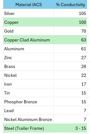
Figure 1
Back to Links
Bonding to the Frame
The intended function of a frame bond is to reduce or equalize Potential Differences between electrical systems and between systems and the metal frame in order to prevent you from becoming the equalizer should there be an electrical fault.This bond should be done using a 2 hole compression lug on an 8AWG conductor.
Remove any paint from the location of the bonding connection.
Run the conductor to a Negative busbar so that all systems may be bonded to the busbar. See Figure 3
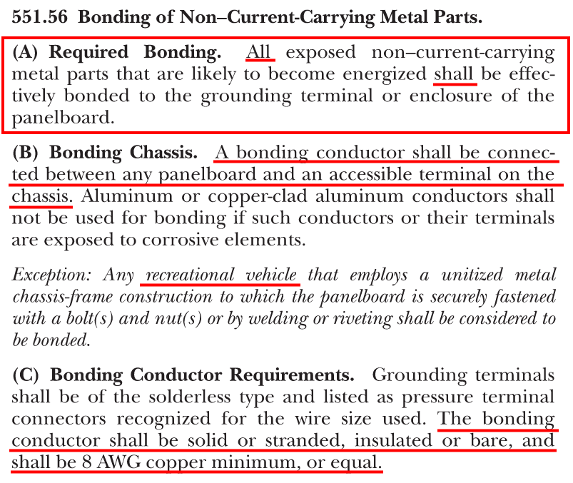
Figure 2
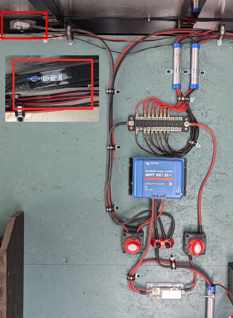
Figure 3
Back to Links
RV Subpanels
There are a couple important reasons why we prefer the use of standard residential subpanels and 12V fuseblocks as opposed to typical all-in-one RV 120/12V panels.
First is space, while the typical RV panel is UL Listed, we do not believe they offer sufficient wire bending space, or room to work in them.
Second is convenience, while having multiple functions in a single package sounds nice, for electrical it can be an expensive issue.
Repairing vs replacing, if one part fails, you typically have to replace the entire unit since finding replacement parts at a reasonable price can be difficult at best.
Third is cost, the typical WFCO unit will run around $150 as a base 30A RV unit with no breakers.
A residential subpanel will run around $30, a 12V fuseblock less than $20, and a small 12V charger (which if you have solar you do not need) less than $60.
Fourth is practicality, if you are going solar you already have a 12V system so adding another 12V system is not needed.
Wiring Your Subpanel
There are two basic options when wiring a 30A/120V panel.Option 1
Figure 4 Option 1This option is best when a transfer switch such as a rotary switch is used as it provides your main disconnect function required by code.
Route main power supply conductor through the first busbar lug and then to the 2nd busbar as shown in Figure 4.
Option 2
Figure 4 Option 2This option is best when a transfer switch is not used and a 30A breaker is installed to act as your main disconnect.
Route main power supply conductor to your 30A breaker and then tie the 2 busbars together with a jumper.
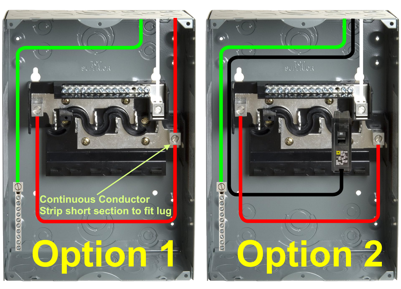
Figure 4
Back to Links
Routing Wires
First and foremost, you do not want to run wires between the outer skin of the trailer and your insulation, the heat that the wires would be subjected to could be a safety/fire hazard.
Easiest way is to route your wire horizontal along the top of the wall using wire clamps to secure every couple feet, then vertical to each outlet. Use aluminum cove to cover wires, then you can easily get to them in the future. Drilling each stud is great in a wood stick frame house, not so much in a metal trailer. See Figure 5
Routing vertical inside walls is a little more work unless you use furring strips to add a little depth to your walls. Often especially in smaller CTCs every inch counts, so channelling your wires is necessary. When you use this method it is best to tape wires in the channel to maintain their route while you re-install panels.
When you need an outlet in a certain location and cannot avoid drilling a metal stud, you must protect that wire as it passes through the stud. This can be done with split loom or bushings. See Figure 6
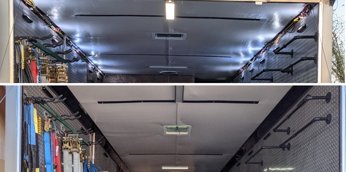
Figure 5

Figure 6
Back to Links
Choosing Electrical Boxes
All boxes have a cubic inch rating stamped in them so an electrician will know how many conductors can safely be in the box, this is for heat dissipation, in other words, Fire Safety.
Also note, the shallow boxes only come with a knockout for a single romex top or bottom, they are not made for multiple romex.
NEC 314.16 Number of Conductors in Outlet, Device, and Junction Boxes, and Conduit Bodies. Boxes and conduit bodies shall be of an approved size to provide free space for all enclosed conductors. In no case shall the volume of the box, as calculated in 314.16(A), be less than the fill calculation as calculated in 314.16(B).
(B) Box Fill Calculations The volumes in paragraphs 314.16(B)(1) through (B)(5), as applicable, shall be added together. No allowance shall be required for small fittings such as locknuts and bushings. Each space within a box installed with a barrier shall be calculated separately.
(1) Conductor Fill Each conductor that originates outside the box and terminates or is spliced within the box shall be counted once, and each conductor that passes through the box without splice or termination shall be counted once. Each loop or coil of unbroken conductor not less than twice the minimum length required for free conductors in 300.14 shall be counted twice. The conductor fill shall be calculated using Table 314.16(B). A conductor, no part of which leaves the box, shall not be counted.
(4) Device or Equipment Fill For each yoke or strap containing one or more devices or equipment, a double volume allowance in accordance with Table 314.16(B) shall be made for each yoke or strap based on the largest conductor connected to a device(s) or equipment supported by that yoke or strap. A device or utilization equipment wider than a single 50 mm (2 in.) device box as described in Table 314.16(A) shall have double volume allowances provided for each gang required for mounting.
(5) Equipment Grounding Conductor Fill Where one or more equipment grounding conductors or equipment bonding jumpers enter a box, a single volume allowance in accordance with Table 314.16(B) shall be made based on the largest equipment grounding conductor or equipment bonding jumper present in the box. Where an additional set of equipment grounding conductors, as permitted by 250.146(D), is present in the box, an additional volume allowance shall be made based on the largest equipment grounding conductor in the additional set.
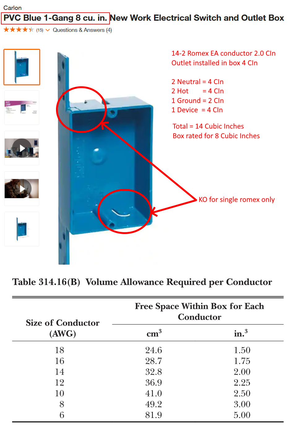
Figure 7
Back to Links
Choosing Correct Wire Gauge
The type of conductor, both the conductor and insulation make a difference in your selection as you can see in the chart below.
The table below will help you choose the correct wire type and gauge for your application.
As you saw in the table above, Cu (copper) is the standard for conductor conductivity at 100%, CCA (Copper Clad Aluminum) is rated at roughly 2/3 of copper or 63% only slightly better than AL (Aluminum) at 61%.
CCA is less expensive making it an attractive option budget wise, but not the best solution electrically speaking.
We do not recommend CCA but if you must use CCA then you need to up size your wire gauge and use less of a load on the circuit, just as if you were using AL conductors.
As with any electrical connection, make sure they are tight and secure, loose connections will create heat and lead to early failure and possibly a fire.
When talking about the length of the circuit, we are referring to total conductor length in DC circuits. This means a device that requires 15 feet of a 2 conductor cable to reach the fuse block is actually a 30 foot circuit. You count both Positive and Negative conductor lengths.
Using the trailer steel as the negative conductor does not eliminate the need to count it as part of the circuit length.
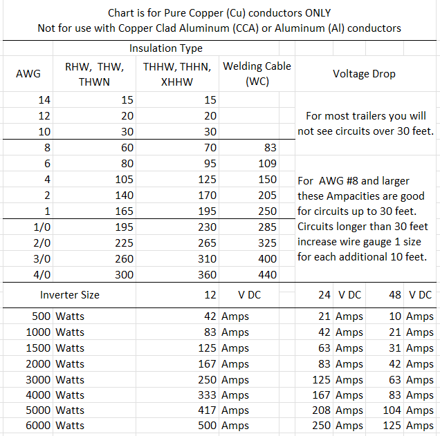
Figure 8
Back to Links
12V Fuses vs Circuit Breakers
We recommend fuses over circuit breakers for 12V systems as fuses tend to me more reliable and accurate and less prone to failure.
Over time CBs can wear which will allow them to withstand higher than rated amperage before tripping, whereas fuses generally retain their amperage rating and blow as indicated.
Size your fuses for the wire gauge they are protecting, and you wire gauge should be chosen based on the load it serves.
Because fuses have a much lower cost, you can usually purchase (6) 200A ANL fuses for less than half the cost of a single 200A CB.
Back to Links
Power for Tankless Water Heaters
Many tankless or instant hot water heaters use batteries for the igniter.
Connecting 3V power to water heater.
An easy way to use your 12V system to power the 3V igniter on the tankless water heater.
We use a step down xfmr like in the link below, it fits perfectly in the battery housing on the unit.
12v Step Down to DC 3V
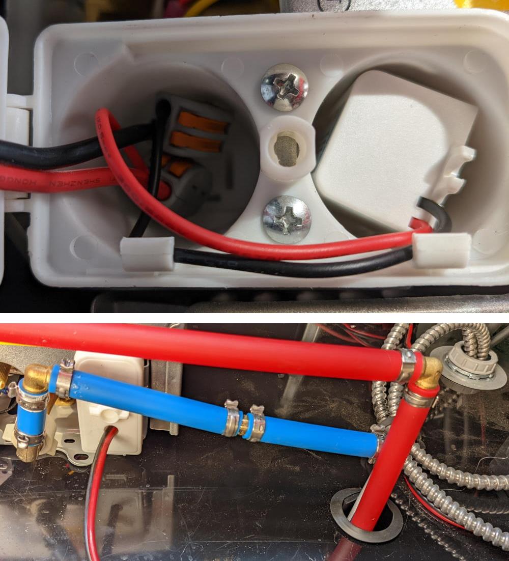
Figure 9
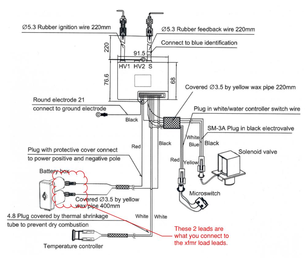
Figure 10
Back to Links
Installing Electrical Boxes in a 1" Stud Wall
When you have 1" studs and 3/8" plywood/OSB paneling, we use a extra shallow 4" square box when installing flush mounted electrical, using a mounting bar and raised industrial covers.
The raised covers are available at most any hardware store and the mounts and boxes are usually available on eBay or Amazon or local electrical supply house.
4in Square Box, 1-1/4" Deep - Brand 1
4in Square Box, 1-1/4in Deep - Brand 2
Box Mounting Bracket - Option 1
Box Mounting Bracket - Option 2

Figure 11
